Content Dev:Scan to CC3+ Wrap Procedures
- Main article: CC Avatar Content Production.
Now comes the bulk of the process where we'll need to use the SelectPointPair node to designate points according to the guides on the CC base body. These points will then be fed into the Wrapping node to conform the shape of the CC base to the scan body. Finally we'll use the Brush node for it's Clone, Project, and Move tools to modify the CC base topology to be more in line with the proper mesh distribution of the original CC animation-friendly topology.
Deploying Point Pairs
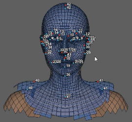
1) Create a SelectPointPairs node and connect it to the Subset and the CC base LoadGeom node. When this node is selected you'll notice that Wrap enters into split view-port; This makes it easier to coordinate the point pairing process.
2) Start pairing the points by carefully clicking on key features of the mesh. Starting from either mesh is fine; just make sure to also designate the match point after laying down the initial point. The points are paired according to the number above the dot markers.
3) Keep adding point pairs until the geometries are sufficiently covered.
4) Create a Wrapping node and connect the CC base Subset node into the first input socket, connect the scan LoadGeom into the second socket, and the SelectPairPoints node into the third. The CC base mesh should turn semi-tranparent and blue.
5) Select the Wrapping node and press the Compute button in the parameters pane, then wait for it to finish calculating. This will conform the CC base mesh to the scan mesh.
Point Pair Placement (Best Practice)
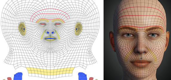
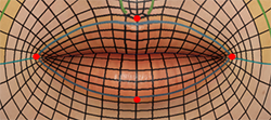
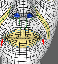
Pay special attention to the outer-edges of the lips (blue guides). By putting points pairs on the outer-edges, mouth shrinkage will be avoided.
Pay attention to the positioning of the nasolabial fold. One point should be positioned at the start of the fold (green line) where it meets the nostrils flaps (alae). The second point should be placed at the end of the fold line and horizontally aligned with the outer-edges of the lips.
Using Brush to Fix Topology
Next step in the process is to use the Brush node to fix various problems with the mesh topology for the wrapped model by using the Clone, Project, and Move tools:
- Clone brush: for changing the topology to resemble the neutral base topology.
- Project brush: for changing the topology to resemble the scan mesh.
- Move brush: can be used to move mesh with a fall-off radius, similar to Maya's Soft Selection. This brush is very useful for modifying the edges of the eyes.
Pay attention to the following:
- The topology should resemble the CC base mesh to mitigate unforeseen issues with facial expressions.
- Use the Relax brush sparingly with great care because the edited topology and edge-flow can deviate from the optimal layout. It's best to avoid it altogether and stick to the tried and true Clone, Project, and Move brushes.
Steps
1) Create a Brush node and connect the Wrapping node to the first socket, the scan mesh LoadGeom to the second socket, the Subset node to the third, and leave the last socket empty.
2) Switch the viewport window to Visual editor and select the newly created Brush node. The brush tip should now be visible in the viewport.
While working with the brush tool, feel free to adjust its settings to your liking such as Radius, Strength, Falloff, etc.
3) Switch to RelaxProj mode (left tool-box) and brush over areas of the mesh where the topology is less evenly distributed such as overly squeezed, distorted, stretched, or crooked mesh.
4) Once areas of the mesh are relaxed, change the brush to Project and go over the same areas to bring them closer to the scan mesh shape.
5) Use the Clone brush to make areas of the mesh go back it's original CC base topological layout.
6) Switch back and forth between the aforementioned brush combinations and work the entire mesh to the desired result. The degree of adjustments depend largely on the results of the wrapping process.
If the mesh is very difficult to fix, then it's probably best to go back to the point pairing stage and readjust the points for a better "Wrapping".
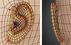
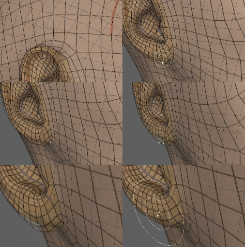
7) Use the Move brush to adjust the shape of the CC base mesh when necessary such as the edges of the earlobe and eyelids.
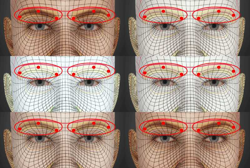
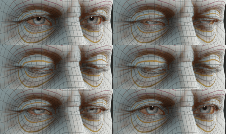
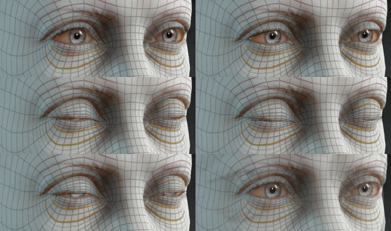
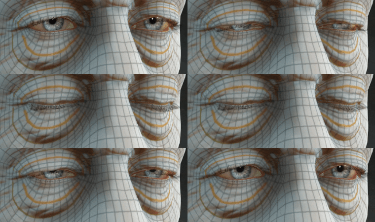
Pay special attention to the mesh around the eyes, you'll need to match the scan as much as possible while keeping the wire-frame evenly distributed to fully support all facial expressions.
8) Click on the Apply button in the parameters pane and switch the view-port to Viewport3D to check the results.
9) Repeat the steps above until the mesh strikes a perfect balance between the shape of the scan mesh and the edge-flow of the CC base body.
Ideal Topology
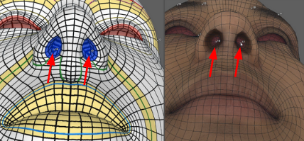
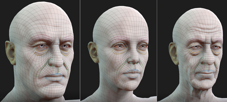
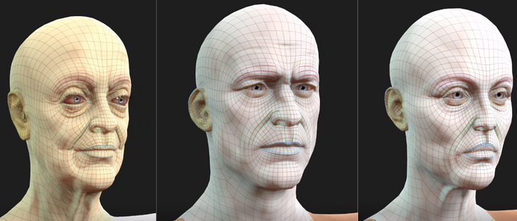
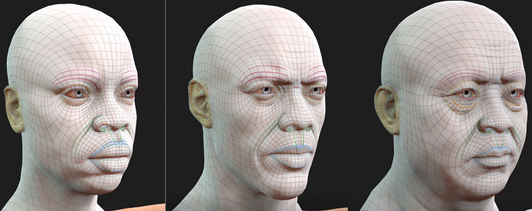
The following are some examples of the ideal mesh topology layout and distribution:
Baking Textures
After you have finished editing the mesh to resemble the scan character without compromising on the animation-friendly edge-flow, you'll need to bake the given textures from the scan to the CC base body:
1) Create a TransferTexture node and plug the first socket to the scan LoadGeom node, second to the Brush node, and leave the third socket empty.
2) Change the TransferTexture node's Width and Height attributes to 4096 pixels.
3) Create an ExtrapolateImage node and connect it to the newly created TransferTexture node.
4) Create a SaveImage node and connect it to the newly created ExtrapolateImage node.
5) Select the SaveImage node and change the File Name attribute by clicking on the browse button to the right: .... Designate a directory to save your texture in and choose a name that is appropriate for your character.
We recommend adding a "_diffuse" suffix to your diffuse map for clarity.
6) Maximize the Quality attribute by typing in "100".
7) Click on the Compute current frame button, and check for the texture map. The diffuse map for the scan character baked according to the CC base UV layout should have been created. Make sure that the texture map resolution is indeed 4096x4096.
8) Click on the LoadImage node that is plugged into the scan LoadGeom node and change the File Name to the normal map that came with your scanned character.
9) Click back to the SaveImage node and change the File Name, this time for saving out the normal map.
We recommend adding a "_normal" suffix to your normal map for clarity.
10) Same as before, click on the Compute current frame to produce the normal map.
11) Repeat the aforementioned steps for other texture maps that came with your scanned character such as Roughness, Thickness, etc.
Blending with the Rest of the Body
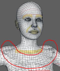
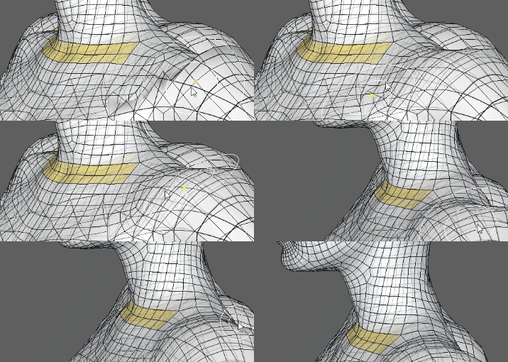
You might have notice by now that we have only dealt with the body from the shoulder up while the rest of the body has been ignored. This has a tendency to cause an abrupt disruption in the wire-fame where the isolated body part is connected to the rest of the body. We'll need to use an ApplySubset to retrieve the entire body and use a Brush node to smoothly transition the wrapped portion of the body to the rest of the body, so that it is completely integrated.
1) Create an ApplySelect node and connect the CC base LoadGeom node into the first socket, Brush node into the second, and SelectPolygons node into the third.
2) Create a new Brush node and plug the ApplySelect node into the first socket, the CC base LoadGeom into the second and the third sockets.
3) Switch to the view-port to Visual editor and use the Clone and Project brush to fix the disrupted topology around the shoulder line.
4) Click on the Apply button once finished and switch to Viewport3D to check the results.
You can check for texture stretching and squeezing by loading the diffuse map created earlier into the CC base LoadImage node and turn off wireframe option on the CC base LoadGeom node.
The Wrap portion of this process is now complete, see CC3+ Prepartion in Maya for the next series of steps.
