Difference between revisions of "Content Dev:CTA4 Character Creation Process"
Chuck (RL) (Talk | contribs) (Created page with "{{TOC}} {{Parent|Content_Dev: CTA_Actor|CTA Actor Creation}} == Head Related Bone Point == File:CTA4_Character_Creation_Workflow_01.png|frame|left|Attempt to symmetrically...") |
Chuck (RL) (Talk | contribs) m (→Facial Angle Image Switch Settings) |
||
| (40 intermediate revisions by the same user not shown) | |||
| Line 4: | Line 4: | ||
== Head Related Bone Point == | == Head Related Bone Point == | ||
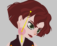
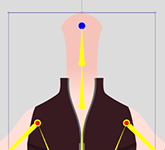
| − | + | The center point of a long object will be placed close to one end for easy rotational adjustments, such as eyebrows and long hair pieces. The ears will be placed at the sides of the face near the center line with the pivot for the eyes aligned with the pupils. The face sides should be placed below the jaw line matching or near the Head Bone point. The Bone point is a one-time settings, so it is urgent to get the settings just right before turning the head. Otherwise, modifications to the Bone point will require modifications to the subsequent head-turn settings and expressions. | |
| − | + | {{Images3 | |
| − | The | + | |image1=CTA4_Character_Creation_Workflow_01.png |
| − | + | |caption1=Attempt to symmetrically align the left and right graphics and bones as much as possible. | |
| + | |image2=CTA4_Character_Creation_Workflow_02.png | ||
| + | |caption2=The neck body part must be stretched to the center point of the face with the '''Head_Nub''' bone point set at its location. | ||
| + | |image3=CTA4_Character_Creation_Workflow_03.png | ||
| + | }} | ||
| − | {{ | + | This setting will let the character turn his/her head while the neck bends according to expectation. |
| + | |||
| + | {{Images3 | ||
| + | |image1= CTA4_Character_Creation_Workflow_04.png | ||
| + | |image2= CTA4_Character_Creation_Workflow_05.png | ||
| + | |image3= CTA4_Character_Creation_Workflow_06.png | ||
| + | }} | ||
| + | |||
| + | == Bone Point Parent Relation == | ||
| + | |||
| + | Please make sure that the object is parented under their corresponding parent items to prevent isolated objects. For example, the bangs should be placed under the '''Front Hair''' and the facial parts should be placed under the '''Face'''. You should name the parts according to their eventual bone names. For example, '''Face > Face2''' means that '''Face2''' is the child bone of '''Face'''. | ||
| + | |||
| + | === Facial Angle Image Switch Settings === | ||
| + | |||
| + | Left and right facial part image switching (like the nose) is designated by the various turning angles in Photoshop. You can download the basic PSD structure template [https://www.reallusion.com/cartoon-animator/PSD-character-animation.html here]. The silhouette for the sides of the face is not constructed from switching images, rather it is composited together from various elements which should be placed under the '''Center''' category. You should place the images in the lowest level directory of each category. For example, inside '''Center > Nose > Normal''' instead of just '''Center > Nose''' or '''Center'''. If placed, say in the '''Center > Nose''' folder, the element may appear inside the '''Composer''' but will become invisible in the '''Stage'''. | ||
| + | |||
| + | {{Images3 | ||
| + | |image1=CTA4_Character_Creation_Workflow_07.png | ||
| + | |caption1=Parent child relation is denoted with a "'''>'''". | ||
| + | |image2=CTA4_Character_Creation_Workflow_08.png | ||
| + | |caption2=angle of the face are composed of '''Left''', '''Right''', and '''Center'''. | ||
| + | |image3=CTA4_Character_Creation_Workflow_09.png | ||
| + | |caption3=Graphic images should always be embedded in the deepest directory of the layer hierarchy. | ||
| + | }} | ||
| + | |||
| + | {{clear}} | ||
| + | |||
| + | [[File:CTA4_Character_Creation_Workflow_10.png|frame|left]] | ||
| + | |||
| + | When creating the left and right side graphics, make sure they remain coherent with the center image. Therefore the parts feel as if they are the left and right side of an object. You can utilize differences in outlines and shadows to consolidate the look of the individual parts like in the figure to the left. | ||
| + | |||
| + | {{clear}} | ||
| + | |||
| + | In order to make the head turn believable, you can place different images for different angles of the face. Then composite it with facial elements to simulate a complete head turn to the side. | ||
| + | |||
| + | {{Images2| | ||
| + | |image1=CTA4_Character_Creation_Workflow_11.png | ||
| + | |image2=CTA4_Character_Creation_Workflow_12.png | ||
| + | }} | ||
| + | |||
| + | {{clear}} | ||
| + | |||
| + | == Head Turn Settings == | ||
| + | |||
| + | You can save some time by creating one side first (either the left or right) for the face turn and mirroring that over to create the opposite side. Some parts such as the eyes, eyebrows and ears have left and right configurations. You can also designate complementary parts using the '''Pairing Settings''' under '''Mirror Options'''. | ||
{{Images2 | {{Images2 | ||
| − | | | + | |image1 = CTA4_Character_Creation_Workflow_13.png |
| − | | | + | |caption1 = The head turn supports 9 different angles: left up and down, center up and down, and right up and down. |
| − | |image2 = | + | |image2 = CTA4_Character_Creation_Workflow_14.png |
| + | |caption2 = Example of the head illustrated head angles. | ||
}} | }} | ||
| − | + | == File Import/Export Settings == | |
| + | |||
| + | Keep in mind that child and parent names should match. For example, '''FrontHair3''' should be placed underneath '''FrontHair''' and not '''Backhair'''. Non-matching names will cause the items to not adopt the movement settings. Size of the PSD graphical elements should also be relatively the same as those in the Cartoon Animator. When the size differences are too great, the movement range will differ significantly when the head turns. If you are unsure of the look for the 45 degree head turn, then it is best to first create the 0 and 90 degree head turn composition. This makes easier to infer the look for the 45 degree head turn and inform you on the facial feature positions and sizes. You can then save the file to preview the head turn and make adjustments to the facial features as needed. | ||
| + | {{images2 | ||
| + | |image1=CTA4_Character_Creation_Workflow_16.png | ||
| + | |caption1=Once you have set the 9 angle points, you can press the save button (highlighted in red) to save the current settings or the current progress. You can also load configured settings using by clicking on the load button (highlighted in blue). | ||
| + | |image2=CTA4_Character_Creation_Workflow_17.png | ||
| + | |caption2=The parent-child relationship is set by the '''HeadBone'''. Please refer to the description of the head related bone point. | ||
| + | }} | ||
| + | |||
| + | == Advanced Process Example == | ||
| + | |||
| + | If you are creating a character in the style of an embedded character, then it is recommended that you first create the quarter view (45 degrees). After you save the foundational settings for the head turn you can process the front view (0 degrees) and the side view (90 degrees). Front and quarter view upward and downward tilt will require the adjustment of facial features and changes to the shape of the face. For the side view, simple head rotation for upward and downward tilt should be sufficient. | ||
| + | |||
| + | === 360 Head Creator Quick Setup === | ||
| + | |||
| + | {{images3 | ||
| + | |image1=CTA4_Character_Creation_Workflow_21.png | ||
| + | |caption1=Once the 45 degree angle is imported, copy them from the blue area to the red area. | ||
| + | |image2=CTA4_Character_Creation_Workflow_23.png | ||
| + | |caption2=Take the left side region and mirror the images over to create the right side opposite angle. | ||
| + | |image3=CTA4_Character_Creation_Workflow_25.png | ||
| + | |caption3=Once the 45 degree angle settings are imported copy them over from the blue area to the red area. | ||
| + | }} | ||
| + | |||
| + | Following the steps above, you'll get results that resemble the following in corresponding order. | ||
| + | |||
| + | {{images3 | ||
| + | |image1=CTA4_Character_Creation_Workflow_20.png | ||
| + | |image2=CTA4_Character_Creation_Workflow_22.png | ||
| + | |image3=CTA4_Character_Creation_Workflow_24.png | ||
| + | }} | ||
| + | |||
| + | After the head is turned, the items that must be placed behind the neck, such as the back, are to be moved to the back of the body. Then move the entire head layer over the body. | ||
| + | |||
| + | [[File:CTA4_Character_Creation_Workflow_27.png|frame|left|For setting the head turn towards the back, make sure that the eyes and nose become compressed. The nose should be moved behind the head and only a slight edge of the mouth is revealed. After copying to the upper and lower cells, rotate to adjust the up and down angles of the head.]] | ||
{{clear}} | {{clear}} | ||
| − | + | == Expression Settings == | |
| + | |||
| + | [[File:CTA4_Character_Creation_Workflow_29.png|frame]] | ||
| + | |||
| + | Please follow the example animation on the left side of the UI to set the amount of displacement for each part of the different parts. | ||
| + | The degree of exaggeration is different depending on the character style. Please set it according to your preference. | ||
| + | There are several items such as the inclination of the eyebrows, the shape of the eyes, the range of movement of the pupils up and down, the amount of twisting of the nose, and the deformation of the mouth. | ||
| + | |||
| + | === Smooth Mode === | ||
| + | |||
| + | Part of the eyes and mouth can choose to use Smooth Mode depending on the role. Different from the preset use of eye-changing/mouth type, Smooth Mode is a combination of multi-object combination, such as the combination of the upper lip of the mouth, the lower lip and the oral cavity into a nutcracker. | ||
| + | Note that after clicking the Smooth Mode, you cannot restore the mode to the original map. Please make sure you need to click again. | ||
| + | |||
| + | {{clear}} | ||
| + | |||
| + | == PSD Creation Process == | ||
| + | |||
| + | After the character PSD is imported, you can see if there is any object on the face that disappears/display error, and then re-import after changing from PS. | ||
| + | If the character you are making has a three-angle body, use the same front head to copy the body to other angles to make the head turn settings. | ||
| + | |||
| + | Then check the parts of the body that have not been cut, and then use the Bone Editor to adjust the Expand to the maximum. | ||
| + | |||
| + | === Body Bone === | ||
| + | |||
| + | For the joint alignment, you can draw a vector full circle with the same curvature in the PSD, using the wrist as an example. The joints on both sides are aligned with this circle. PSD into the AP will automatically ignore the vector file, can be retained. Change the gesture to pay attention to whether each gesture has a vector circle for reference. | ||
| + | |||
| + | === Foot Angle === | ||
| + | |||
| + | It is recommended that if you want to place a new angle graphic, you can put the outer opening, front, inner eight, and positive side feet from top to bottom. | ||
| + | |||
| + | === Skeleton === | ||
| + | |||
| + | When making a new character skeleton, be aware that the three points of Thigh/Shin/Foot should be arranged in a non-linear manner to be able to manually operate the character. | ||
| + | There is a slight difference in value (1pixel). If it is a straight line, the action character will go to either side. An angled situation will be fixed to the left and right. | ||
| + | |||
| + | Unless necessary, such as the shape of the foot of the shoe, the distance between the ankle and the sole (Foot/Foot2) should not be too far away. If it is too far, it will easily cause the deformation of the skeleton of the operating foot skeleton when the Lock toe is moved. | ||
{{Images3 | {{Images3 | ||
| − | |image1= | + | |image1=CTA4_Character_Creation_Workflow_39.png |
| − | |image2= | + | |caption1=The knee should have a slight angle. |
| − | |image3= | + | |image2=CTA4_Character_Creation_Workflow_40.png |
| + | |caption2=If the knee is completely straight, the inverse kinematics can flip to the wrong side. | ||
| + | |image3=CTA4_Character_Creation_Workflow_41.png | ||
| + | |caption3=A slight angle to the knee ensures that the inverse kinematics angle toward the right directions. | ||
| + | }} | ||
| + | |||
| + | === Hand Gestures Appendix === | ||
| + | |||
| + | Take the right hand as an example, with 30 gestures on one side and mirror shots on the left hand. Note that gestures have back and under side differences. | ||
| + | |||
| + | {{Images2 | ||
| + | |image1=CTA4_Character_Creation_Workflow_45.png | ||
| + | |caption1=Back Side | ||
| + | |image2=CTA4_Character_Creation_Workflow_46.png | ||
| + | |caption2=Under Side | ||
}} | }} | ||
Latest revision as of 01:34, 19 July 2019
- Main article: CTA Actor Creation.
Head Related Bone Point
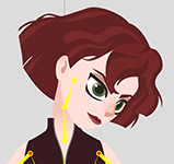
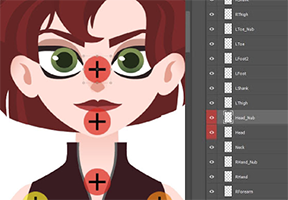
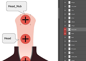
The center point of a long object will be placed close to one end for easy rotational adjustments, such as eyebrows and long hair pieces. The ears will be placed at the sides of the face near the center line with the pivot for the eyes aligned with the pupils. The face sides should be placed below the jaw line matching or near the Head Bone point. The Bone point is a one-time settings, so it is urgent to get the settings just right before turning the head. Otherwise, modifications to the Bone point will require modifications to the subsequent head-turn settings and expressions.
-
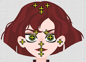 Attempt to symmetrically align the left and right graphics and bones as much as possible.
 -
 The neck body part must be stretched to the center point of the face with the Head_Nub bone point set at its location.
 -
This setting will let the character turn his/her head while the neck bends according to expectation.
Bone Point Parent Relation
Please make sure that the object is parented under their corresponding parent items to prevent isolated objects. For example, the bangs should be placed under the Front Hair and the facial parts should be placed under the Face. You should name the parts according to their eventual bone names. For example, Face > Face2 means that Face2 is the child bone of Face.
Facial Angle Image Switch Settings
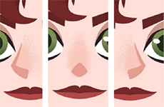
Left and right facial part image switching (like the nose) is designated by the various turning angles in Photoshop. You can download the basic PSD structure template here. The silhouette for the sides of the face is not constructed from switching images, rather it is composited together from various elements which should be placed under the Center category. You should place the images in the lowest level directory of each category. For example, inside Center > Nose > Normal instead of just Center > Nose or Center. If placed, say in the Center > Nose folder, the element may appear inside the Composer but will become invisible in the Stage.
-
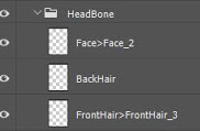 Parent child relation is denoted with a ">".
 -
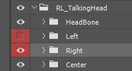 angle of the face are composed of Left, Right, and Center.
 -
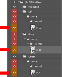 Graphic images should always be embedded in the deepest directory of the layer hierarchy.
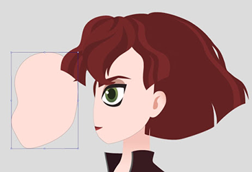
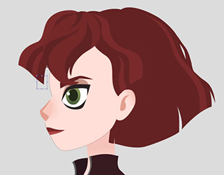
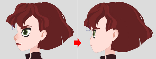
When creating the left and right side graphics, make sure they remain coherent with the center image. Therefore the parts feel as if they are the left and right side of an object. You can utilize differences in outlines and shadows to consolidate the look of the individual parts like in the figure to the left.
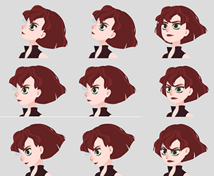
In order to make the head turn believable, you can place different images for different angles of the face. Then composite it with facial elements to simulate a complete head turn to the side.
Head Turn Settings
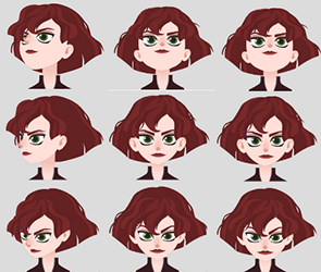
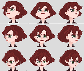
You can save some time by creating one side first (either the left or right) for the face turn and mirroring that over to create the opposite side. Some parts such as the eyes, eyebrows and ears have left and right configurations. You can also designate complementary parts using the Pairing Settings under Mirror Options.
-
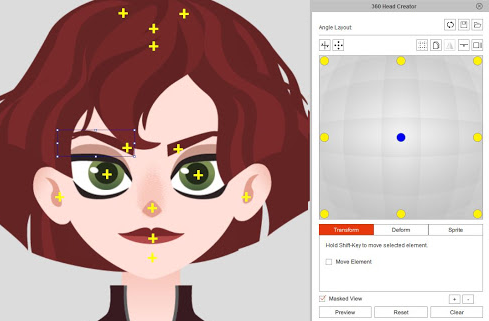 The head turn supports 9 different angles: left up and down, center up and down, and right up and down.
 -
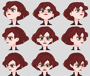 Example of the head illustrated head angles.
File Import/Export Settings
Keep in mind that child and parent names should match. For example, FrontHair3 should be placed underneath FrontHair and not Backhair. Non-matching names will cause the items to not adopt the movement settings. Size of the PSD graphical elements should also be relatively the same as those in the Cartoon Animator. When the size differences are too great, the movement range will differ significantly when the head turns. If you are unsure of the look for the 45 degree head turn, then it is best to first create the 0 and 90 degree head turn composition. This makes easier to infer the look for the 45 degree head turn and inform you on the facial feature positions and sizes. You can then save the file to preview the head turn and make adjustments to the facial features as needed.
-
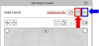 Once you have set the 9 angle points, you can press the save button (highlighted in red) to save the current settings or the current progress. You can also load configured settings using by clicking on the load button (highlighted in blue).
 -
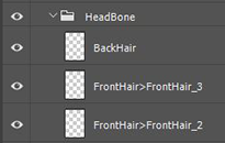 The parent-child relationship is set by the HeadBone. Please refer to the description of the head related bone point.
Advanced Process Example
If you are creating a character in the style of an embedded character, then it is recommended that you first create the quarter view (45 degrees). After you save the foundational settings for the head turn you can process the front view (0 degrees) and the side view (90 degrees). Front and quarter view upward and downward tilt will require the adjustment of facial features and changes to the shape of the face. For the side view, simple head rotation for upward and downward tilt should be sufficient.
360 Head Creator Quick Setup
-
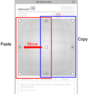 Once the 45 degree angle is imported, copy them from the blue area to the red area.
 -
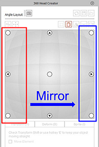 Take the left side region and mirror the images over to create the right side opposite angle.
 -
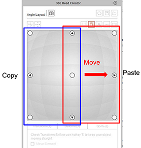 Once the 45 degree angle settings are imported copy them over from the blue area to the red area.
Following the steps above, you'll get results that resemble the following in corresponding order.
After the head is turned, the items that must be placed behind the neck, such as the back, are to be moved to the back of the body. Then move the entire head layer over the body.
Expression Settings
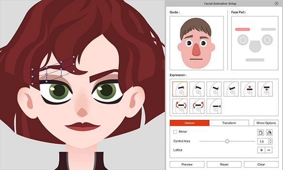
Please follow the example animation on the left side of the UI to set the amount of displacement for each part of the different parts. The degree of exaggeration is different depending on the character style. Please set it according to your preference. There are several items such as the inclination of the eyebrows, the shape of the eyes, the range of movement of the pupils up and down, the amount of twisting of the nose, and the deformation of the mouth.
Smooth Mode
Part of the eyes and mouth can choose to use Smooth Mode depending on the role. Different from the preset use of eye-changing/mouth type, Smooth Mode is a combination of multi-object combination, such as the combination of the upper lip of the mouth, the lower lip and the oral cavity into a nutcracker. Note that after clicking the Smooth Mode, you cannot restore the mode to the original map. Please make sure you need to click again.
PSD Creation Process
After the character PSD is imported, you can see if there is any object on the face that disappears/display error, and then re-import after changing from PS. If the character you are making has a three-angle body, use the same front head to copy the body to other angles to make the head turn settings.
Then check the parts of the body that have not been cut, and then use the Bone Editor to adjust the Expand to the maximum.
Body Bone
For the joint alignment, you can draw a vector full circle with the same curvature in the PSD, using the wrist as an example. The joints on both sides are aligned with this circle. PSD into the AP will automatically ignore the vector file, can be retained. Change the gesture to pay attention to whether each gesture has a vector circle for reference.
Foot Angle
It is recommended that if you want to place a new angle graphic, you can put the outer opening, front, inner eight, and positive side feet from top to bottom.
Skeleton
When making a new character skeleton, be aware that the three points of Thigh/Shin/Foot should be arranged in a non-linear manner to be able to manually operate the character. There is a slight difference in value (1pixel). If it is a straight line, the action character will go to either side. An angled situation will be fixed to the left and right.
Unless necessary, such as the shape of the foot of the shoe, the distance between the ankle and the sole (Foot/Foot2) should not be too far away. If it is too far, it will easily cause the deformation of the skeleton of the operating foot skeleton when the Lock toe is moved.
-
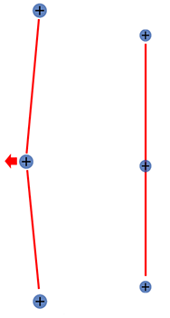 The knee should have a slight angle.
 -
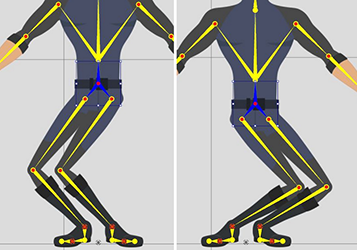 If the knee is completely straight, the inverse kinematics can flip to the wrong side.
 -
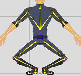 A slight angle to the knee ensures that the inverse kinematics angle toward the right directions.
Hand Gestures Appendix
Take the right hand as an example, with 30 gestures on one side and mirror shots on the left hand. Note that gestures have back and under side differences.
-
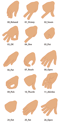 Back Side
 -
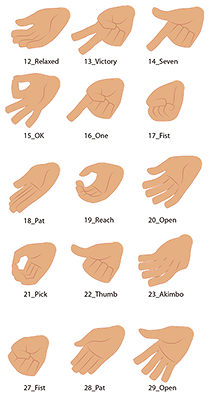 Under Side
